Industrial Controller Repair
EEC510 electron beam controller: blown tantalum capacitor, failed switching regulator and unstable internal USB link
A tantalum capacitor on an EEC510 electron beam controller's I/O board had burst, and the switching regulator beside it had failed. We replaced both and the unit powered up normally. Communication errors with the I/O board then showed up at start-up: the I/O board's USB-to-serial bridge was not always recognised. Without rewriting the original software, we changed the BIOS USB mode and connected the I/O board to the PC board's second USB-A port with a new cable; three cold starts in a row passed.
PN 225906 · LM2575S-ADJ Switching Regulator · 68 µF 20 V Tantalum Capacitor · FT4232HL USB Link · 3 Cold Starts Passed
- Engineering category
- Industrial Controller Repair
- Equipment model
- EEC510 electron beam controller
- Service
- Industrial Controller Repair
- Repair date
- October 2026
The repair, step by step
Part 1 · Power supply repair
Illustrative 3D model drawn in code to explain the repair. Not a photograph of the customer's equipment.
1Damage found
A component on the board has visibly burst.
2Capacitor replaced
The blown 68 µF 20 V tantalum capacitor is removed and a new one fitted.
3Regulator tested
Checks around it show the LM2575S-ADJ switching regulator has also failed.
4Regulator replaced
A new regulator IC is soldered in.
5Power-on test
The unit starts, the display shows system information and the indicator lights.
Part 2 · Communication fault
Illustrative 3D model drawn in code to explain the repair. Not a photograph of the customer's equipment.
1Fault reproduced
At some starts the I/O board's USB bridge is not recognised; four serial ports missing, READY blinks.
2Link traced
CN18 → white cable → J10 → U1 → IC19 traced; voltages around U1 checked against J9 GND.
3BIOS changed
xHCI enabled, USB 2.0 (EHCI) support disabled.
4USB rerouted
White cable off J10; new USB A-B cable from the second USB-A port to J10.
53 cold starts
All four ports come up by themselves every time; READY stays lit. Full machine test still to be done.
01
Problem description
A component on the controller's I/O board had visibly burst. The unit also showed communication errors with its I/O board; after a restart, communication came back only briefly.
02
Confirmed findings
- The burst part was a 68 µF 20 V tantalum capacitor in the board's power supply.
- The LM2575S-ADJ step-down switching regulator next to it had also failed.
- With the power supply repaired, the unit starts: BIOS, Linux and the controller software (EEC500 v3.007) load, and the network port links at 1 Gbps.
- Communication fault reproduced: at some starts the FT4232HL USB-to-serial bridge on the I/O board was not enumerated, so its four USB serial ports did not appear and the controller software could not connect to the I/O board.
- The internal link was traced on the unit: PC board header CN18 → white internal USB cable → I/O board J10 → FT4232HL (U1) → H8S controller (IC19).
- Voltages around U1, measured against J9 GND, read about 1.80 V and 3.6 V with no steady loss of supply at the points checked.
- With the link up, the I/O board answered correctly (firmware version and status replies), so the bridge-to-controller path itself works.
- Some test cables failed USB enumeration (descriptor errors) while others worked; the original CN18 path still failed some cold starts after the BIOS change.
03
Likely cause (not confirmed)
- Power supply: not confirmed from the record. A shorted tantalum capacitor can overload the regulator next to it, but which of the two parts failed first was not established.
- Communication: not confirmed. The fault is an intermittent USB enumeration problem on the internal CN18 → J10 path at start-up; which part (header, cable, or the timing on either board) is to blame was not proven.
04
Repair / engineering method
- Replaced the 68 µF 20 V tantalum capacitor.
- Replaced the LM2575S-ADJ switching regulator.
- Changed the BIOS USB setting: xHCI enabled, USB 2.0 (EHCI) support disabled.
- Disconnected the original white internal cable from J10 only (left in place at CN18) and connected J10 to the PC board's second USB-A port with a new USB A-to-B cable.
- No board, chip or EEPROM was replaced for the communication fault, and no firmware, system or control program was rewritten; the key program, kernel and start-up files match the original image.
- Also delivered a separate read-only monitoring tool that shows the link, USB state, I/O values and logs over the network.
05
Tests performed
- Power-on test passed: the unit started up and its display and indicator worked.
- Three cold starts (power off 30 s, 30 s and 120 s): each time the four USB serial ports appeared on their own, the controller software connected, the READY lamp stayed lit, and no USB errors or disconnects were logged.
- 35 status samples across the three starts all showed the I/O board connected, with fresh data each time.
- Not tested: the full electron-beam control functions on the customer's complete machine (remote control, crucible drive, water, high voltage, filament and all physical I/O).
06
Images
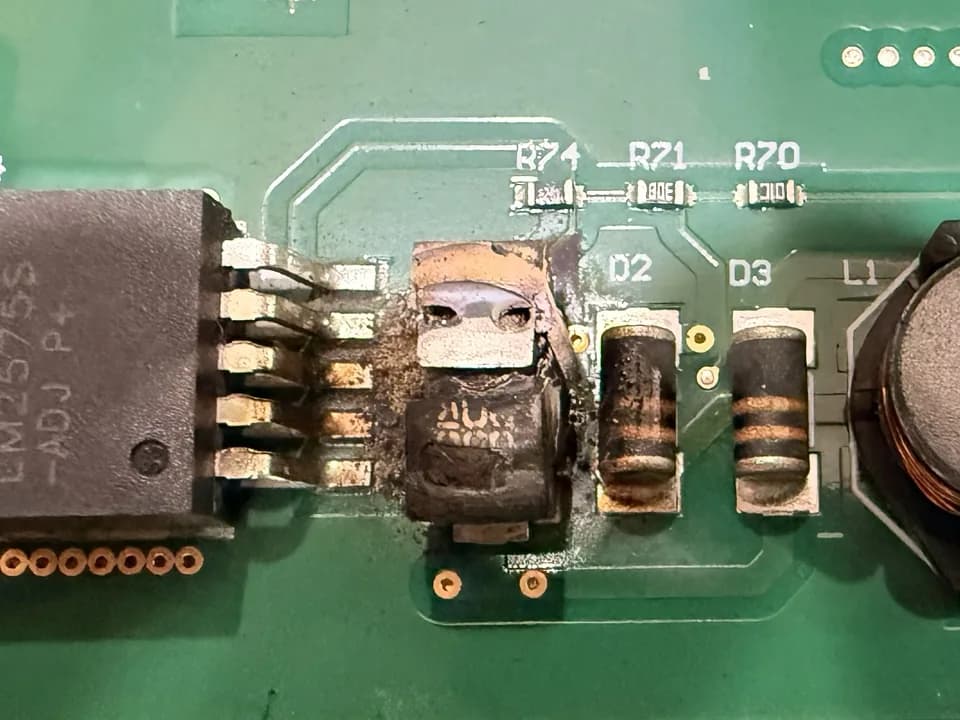
As received: the burst capacitor next to the regulator 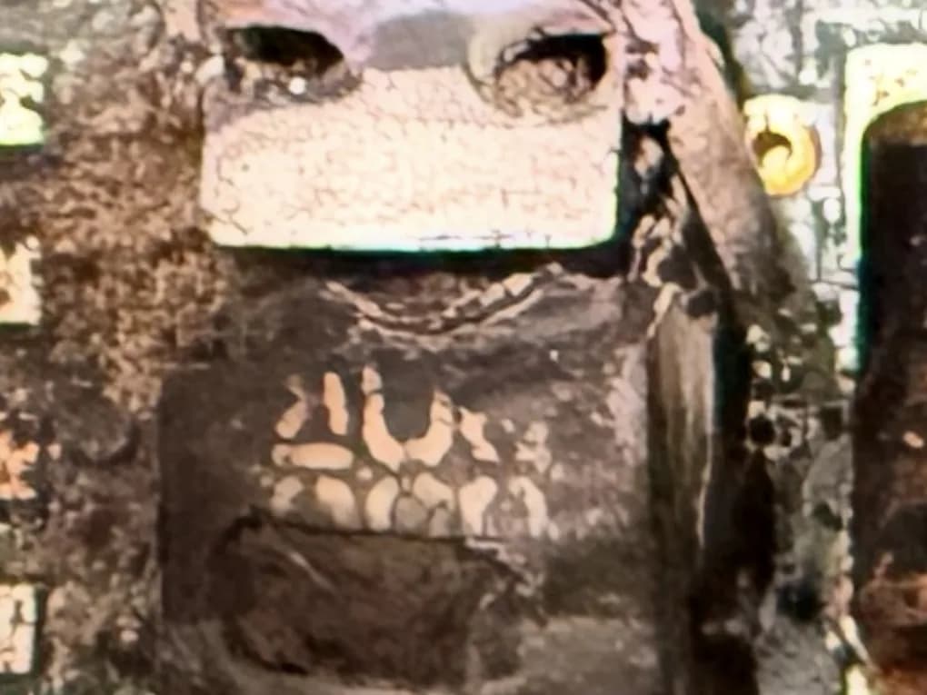
Close-up of the burst capacitor 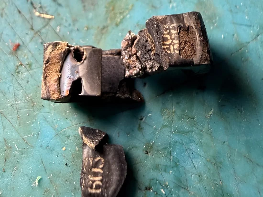
The failed capacitor after removal 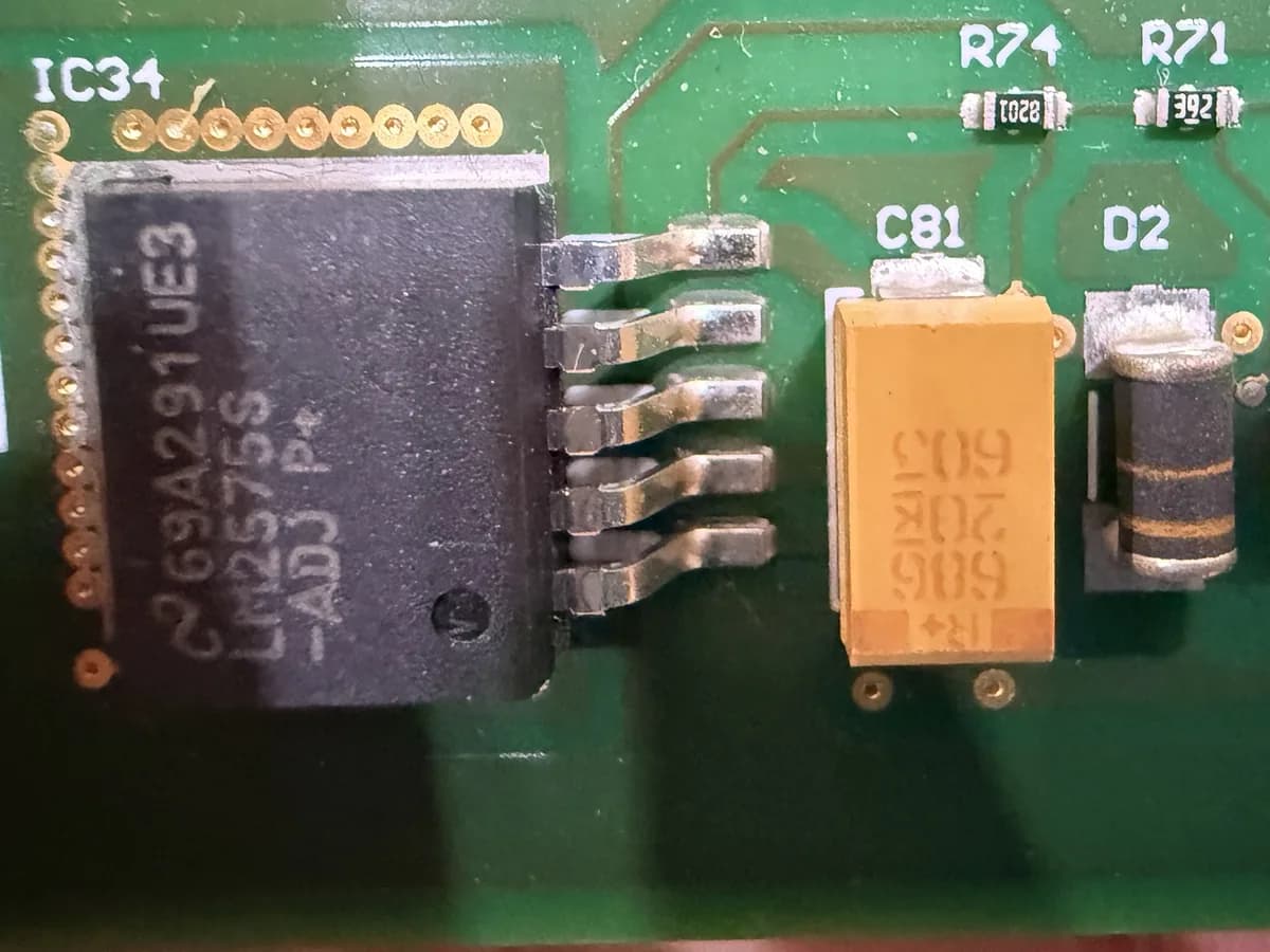
After repair: new regulator and new capacitor
07
Final result
Both failed power-supply parts replaced, and the controller now starts communication with the I/O board on every cold start tested, using a rerouted USB link and no changes to the original software. The root cause of the intermittent fault on the original USB path is not yet confirmed.
Manufacturer and model names are used only to identify the equipment we repaired. All trademarks belong to their owners; X TRONIC AUTOMATION is an independent repair service and is not affiliated with or endorsed by the manufacturer.
Request for Quotation
Have a failed board, controller or machine?
Send us the manufacturer, model or part number and a description of the fault. Our technical team will review it and respond with the next steps.